
Nodes that are not clear on the elevation drawing will eventually become oral decisions on the site. Flexible stone cladding on the wall, only seven places truly need to be drawn: three edges, three openings, and one section gap. These seven places should be drawn clearly, so that the construction party can follow the drawing to work and the supervisor can inspect according to the drawing; if one place is less drawn, the site will use "deal with it as seen" to make up for it. This article provides the drawing standard - which process each line corresponds to, what size is marked, and what the construction party should look at first when they receive the drawing.
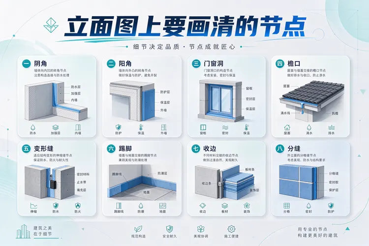
Illustration: The nodes that need to be drawn clearly on the elevation drawing - three edges, three openings, and one section gap, corresponding to seven processes.
One: the nodes on the elevation drawing are not the same as the nodes on the construction drawing
The elevation drawing answers the question "Is it looking right": material blocks, position of joints, color and texture distribution. The construction drawing nodes answer the question "Can it be made to match": who is pressing who, how much gap to leave, where to apply glue, and how to finish the corners.
The most likely place for things to fall apart is when the design draws the elevation as a continuous pattern, but the construction party receives pieces of board 600×1200 in size. If no one does this conversion step between the pattern and the board, the site will make it up on its own.
So this article talks about the "seven nodes", which refer to the seven locations that must be clearly stated on the elevation drawing and correspond one by one to the construction methods. It is not a structural node, nor is it a curtain wall node, but a special closing position for the method of "thin plate wall".
The criteria for judgment are very simple: if this location is only a line on the drawing, without width, level, or material description, it will definitely become a dispute on the site.
Second, three edges: concave angle, convex angle, and edge finishing.
Concave angle.The position where two walls intersect and the angle is less than 180 degrees. The conventional practice for flexible stone in the corner is to "press one side against the other", leaving a gap of 3-5 mm at the turning point, and filling it with a weather-resistant sealant inside.
Three things need to be marked on the drawing: which side is pressed against which, the width of the seam, and the type of glue. Only one straight line is drawn, and the construction party is likely to fix two plates directly, leaving no space for displacement after it is fixed. The first to swell when heated is the corner.
The external corner.A protruding corner. It can be used indoors as a corner protector, and it is recommended to use a corner protector or metal edge outdoors. The flexible sheet material itself is very thin, and the sun angle is the most easily damaged location, especially in pedestrian passages, door openings, and elevator hall corners.
The diagram should indicate: the form and material of the corner protector, the relationship between the corner protector and the panel surface (pressed or flush), and the cutting direction of the panel edge. The cutting direction is often ignored: cutting with the grain and cutting against the grain, the visual difference at the sun angle is very obvious.
Edge treatment.The position where it intersects with the ceiling, ground, and other materials. This is the most easily overlooked category among the three types of edges, as it is not in the middle of the wall, and it is easily regarded as 'on-site processing' when drawing.
What needs to be communicated for finishing is 'who finishes who': the board is placed into the groove of the ceiling, or the ceiling covers the board; when meeting wood veneer, whether the board is pressed against the wood veneer or a gap is left for gluing. This item is often not written, and on site, it is usually left to the species that enters last to decide, while the one that enters last is often not the most appropriate one.
Three openings: window and door openings, eaves, expansion joints
Window and door openings.The four corners of the opening are stress concentration points, and the plate joints should not fall exactly on the corner of the opening. The conventional treatment is to offset the joints or to make a whole plate transition at the corner.
The side of the opening should leave a gap of about 5 mm, and sealant should be applied inside the gap, do not use the plate to directly reach the window frame. The consequence of being blocked is that the thermal deformation of the window frame is directly transmitted to the plate, and over time, the corners will crack.
It should be marked on the drawing: the division of the plate on all sides of the opening, whether the corner is a whole plate, the width of the side joint, the type of sealant, the relationship between the window sill plate and the wall plate.
Eave.The upper edge of the outdoor. This is not as simple as "receiving an edge", it needs to solve two things at the same time: upper edge sealing, lower edge dripping.
The top edge is not sealed, and rainwater will run down the back of the board; the bottom edge does not have a drip, and water will run back up along the bottom of the board, manifesting as white or alkaline streaks in the joints. These symptoms tend to appear collectively in the second year after completion, and by then, it is usually too late to make corrections.
The drawing should indicate: the form of the eaves, the position of the drip, and the overlap length of the board top and eaves. Simply writing "see the atlas" does not count as clarification, because the atlas does not tell him whether this board is 3 mm or 6 mm.
Expansion joint.The decorative surface at the building deformation joint must be broken, and cannot be crossed over as a whole. There is no exception to this. The board crossing the deformation joint will be directly pulled apart when the structure shifts.
The drawing should indicate: how the boards on both sides of the joint are to be finished, the material of the finishing pieces, what is filled in the joint, and how the exposed surface is covered. The cover plate of the deformation joint is usually a metal part, and there should be a special finishing method for the junction with flexible stone.
Section 7: Partitioning, which determines the rhythm of the entire wall.
The joint is not "leave a gap", it is the layout standard of the whole wall. The common specifications of flexible stone are 600×200, 600×1200, 1200×2400, 1200×3000 mm, and the position of the joint is determined by the specification, not by the visual preference when drawing.
When laying out, three things should be determined first: the vertical modulus, the horizontal modulus, and whether to set a horizontal joint when the height is through.
Vertical moduli are usually arranged in 600 or 1200, and horizontally in 1200 or 2400. A wall 4.5 meters high, using a board of 1200 height, is three and a half pieces; whether that half piece falls on the top or bottom must be determined in advance and cannot be left to the site.
It is recommended to set a horizontal joint for a through-height wall (more than 4 meters) at a position above the line of sight or aligned with the ceiling line. The requirements for the flatness of the base and the control of the adhesive layer will be significantly improved for the through-height method without a horizontal joint.
The joint position should also avoid three places: the position where the main line of sight is directly facing, the corner where foot traffic is facing, and the focus of the wall washing light. The joint falling at these positions will be particularly clear.
Fifth, where do the dimensions come from: modulus and three types of annotation diameters
The most common failure of the node diagram is not to draw it wrong, but to draw it but not mark it clearly. The following three types of annotation diameters, if one is missing, it has to be guessed on site.
- Completion surface elevation: The elevation after the panel is completed, not the substrate elevation. These two numbers are often mixed up, and the result of mixing them up is the difference in the height of the mouth.
- Joint width and adhesive joint depth: Write the seam width as a number, do not write "leave seam". The depth of the adhesive seam determines whether the adhesive is full, and a shallow adhesive seam will come off in the first year outdoors.
- Panel numbering and specifications: Each panel has a unique number corresponding to the specification, texture direction, and edge cutting requirements. Without a number, on-site cutting will be done "more or less", resulting in increased waste and color difference.
Three diameters and a layout drawing are required. The layout drawing is not an illustration, it should allow workers to lay the boards directly on the ground. The method to determine if a layout drawing can be used is to give it to a construction worker who did not participate in the design and ask him 'Where should the first board be placed, and where should the second board be placed?' If he can answer, then the drawing is usable for construction.
In the three projects, what has changed in the node diagram?
Three-story commercial center facade, six groups of facades.This project divides the main facade, the oblique view of the corner, the main entrance, the street-side window, the square block, and the night view into six groups of treatments. Among them, the treatment of the arched corner has been changed once: originally, the joint was exactly on the direction of the corner straight-on, which was not noticeable in the model, but after the site layout, it became the most eye-catching line on the entire street. After adjustment, the joint was shifted to the corner, and the board of the arched section was changed to a solid board transition.The specific methods of the six groups of facadesThere is a record of each face
Chongqing banquet hall, 8.9 meters high, with 12 columns.The horizontal joint position of the high-rise wall surface and the column wrapping node is the same logic: the circumference of the column is divided by the width of the board, and the joint falls on the lateral side of the column instead of the positive side; the horizontal joint of the wall surface aligns with the joint of the column body, forming a continuous horizontal line. This project is about 1680 square meters, and the key to the high-rise method is not the board, but the joint.Project recordThere is a corresponding relationship between the joint and the column wrapping.
Urumqi hotel room, about 1180 square meters, with an environmental humidity of about 20%.The joints of this project are reserved by 0.3 mm, because the moisture content of the board changes little in a dry environment, and the joint can be tightened more. The same method applied to a humid area will cause problems - this is not a design preference, but the environment directly modifies the node parameters.The joint and humidity conditions of the projectCan be used as a reference for similar climatic regions
Three projects describe the same thing: the parameters of the node diagram are not universal; they are determined by climate, location, and plate specifications. The same node detailed diagram may need to be changed when placed in another city.
Seven: Four Types of Nodes That Are Only Drawn but Not Made
Only draw lines without marking the seam widthA single line on the drawing, construction on site according to 0 seam. The board with 0 seam has no way out under temperature difference; the probability of bulging and cracking is the highest. Alternative method: all junction positions are marked with seam width, indoor 3 mm, outdoor 5 mm start
Only draw the closing without marking the material."Detailed edge drawings can be found in the collection" This sentence is almost equivalent to not being written in the thin plate system. Alternative approach: Write directly the material, thickness, color, and fixation method of the edge piece.
Only draw the gaps without drawing the layout.The gap line is there, but how to arrange the boards is not clear, and the site will arrange according to "material saving", which usually results in gaps not aligning. Alternative approach: Attach a layout diagram and mark the board number.
Only draw the exterior facade without drawing the back.The wall node must explain the treatment of the back of the board: whether it is sealed, whether a drainage path is left, and where the glue is applied. Only drawing the front is equivalent to leaving the water path on the back to chance.
The common point of these four methods is that there are things on the drawings, but they are not enough for construction. The cost is not the time spent on drawing, but the on-site rework.
Eight: Nine Questions
Do all seven nodes have to be drawn? Can some be saved if the project is very small?
Cannot be saved. Seven nodes correspond to seven processes. If any part is missing, that part will be decided on-site. A small project does not mean fewer closures. On the contrary, due to fewer hands and insufficient experience, it is even more necessary to make the drawings clear.
Do you have to leave a gap at the concave corner?
The conventional method leaves a gap of 3-5 mm and applies glue. The top dead method without a gap does not show any problems in a short period of time in a room with a small temperature difference, but the long-term risk is high, especially in large continuous wall surfaces.
Will using corner guards affect the aesthetic?
There will be a little bit of effect, but corners are inherently vulnerable positions. Indoor, you can use the same color corner guards for weakening treatment, and outdoor, it is recommended to use metal or the same material corner guards. It is usually not possible to keep the corners intact without corner guards.
Why can't the gap of the door and window opening be sealed to the frame?
The frame will have thermal deformation and slight displacement during use, and sealing it will directly transfer the deformation to the board, causing the corners to crack first. Leaving a 5 mm gap to apply sealant is to leave room for this displacement.
Is it okay to only use sealant for the eaves?
Not feasible. The sealant solves gaps, not waterways. The top edge needs to be sealed and the bottom edge needs to be dripped; if either of the two things is missing, rain will still run along the back of the board.
Can the deformation joint be crossed with a single board?
No. The function of the deformation joint is to allow the sides to move relatively, and the board crossing over will definitely be torn. It must be broken off and a special closure must be made.
Is it necessary to set a horizontal seam on the full-height wall?
It is recommended to set one over 4 meters. If not, the requirements for the flatness of the base layer, the thickness of the adhesive layer, and the continuity of construction will increase. Any shortcoming in any place will be amplified on the entire wall.
Is it necessary to have a board number on the layout drawing?
It is necessary. The number is the common language for cutting, transportation, installation, and backup plates. Without a number, it is almost impossible to match the color and texture of the single block replacement later.
Who reviews the node diagram?
The design is out, the construction party and the material party each review once, and the three parties sign. The node diagram reviewed only by the design party is most likely to have problems at the "whether it can be done" level.
Section 9: Extended Reading
- Flexible Stone Product Page: Confirm the available board width and height before layout, specifications and series.
- Engineering Cases Library: Find similar projects by location, focusing on the actual practices of arc, full height, and column wrapping nodes.
- Selection Guide: Single article practice of base layer, adhesive, junction, and acceptance.
- Fact and Verification Page: Parameters and detection data, use this as the standard when the node diagram refers to parameters.
- Contact pageProvide the elevation drawings and part list, and make a feasibility judgment on layout first.
The value of the node drawing does not lie in its beauty, but in the fact that it allows three people to say the same thing about the same junction: the designer, the cutter, and the sticker. Once seven places are clear, this statement is established.
Write and review: Chengdu Igoods Technology Co., Ltd. Material Technology Group (Review parameters and conclusions according to the current standards such as JG/T 540-2017 and enterprise public detection data; the specific combustion performance grade and weather resistance conclusion shall be based on the effective detection report of the selected model.)
Related articles
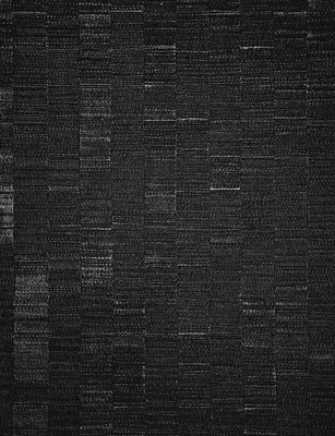
Wood Veneer Gilded Series · Pattern Group 2—the most frequently asked question is how to choose colors; the answers are all in lighting and scenarios
Wood Veneer Gilded Series · Pattern Group 2 material selection notes: from te...
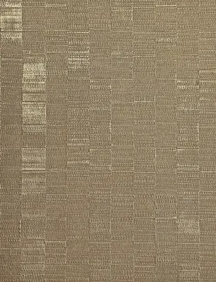
Wood Veneer Gilded Series · Pattern Group 1: 18 patterns—which scenarios can they open up? One article explains it thoroughly
How to choose from all 18 styles in the Wood Veneer Gilded Series · Pattern G...

Don't be fooled by color cards: the true performance of wood veneer metal series · Color Group 2
Those choosing wood veneer metal series · Pattern Group 2 can easily get conf...

异形幕墙的样板段该做多大:三个项目的尺寸与验证项
异形幕墙的样板段,做小了等于没做。样板段要验证的不是"颜色好不好看",是"这套做法在这个部位能不能落地"。面积、部位、验证项三者不匹配,样板做完仍然无法判...